- 您现在的位置:买卖IC网 > Sheet目录337 > LH28F320SKTD-ZR (Sharp Microelectronics)IC FLASH 32MBIT 70NS 48TSOP
�� �
�
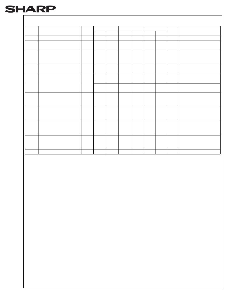
�LHF32KZR�
�DC� Characteristics� (Continued)�
�38�
�V� CC� =2.7V�
�V� CC� =3.3V�
�V� CC� =5V�
�Test�
�Sym.�
�Parameter�
�Notes� Min.�
�Max.�
�Min.�
�Max.�
�Min.�
�Max.� Unit�
�Conditions�
�V� IL�
�V� IH�
�Input� Low� Voltage�
�Input� High� Voltage�
�7�
�7�
�-0.5�
�2.0�
�0.8�
�V� CC�
�+0.5�
�-0.5�
�2.0�
�0.8�
�V� CC�
�+0.5�
�-0.5�
�2.0�
�0.8�
�V� CC�
�+0.5�
�V�
�V�
�V� OL�
�Output� Low� Voltage�
�3,7�
�V� CC� =V� CC� Min.�
�0.4�
�0.4�
�0.45�
�V�
�I� OL� =2mA� (2.7V,� 3.3V)�
�5.8mA� (5V)�
�V� OH1�
�V� OH2�
�Output� High� Voltage�
�(TTL)�
�Output� High� Voltage�
�(CMOS)�
�3,7�
�3,7�
�2.4�
�0.85�
�V� CC�
�2.4�
�0.85�
�V� CC�
�2.4�
�0.85�
�V� CC�
�V�
�V�
�V� CC� =V� CC� Min.�
�I� OH� =-2.5mA�
�V� CC� =V� CC� Min.�
�I� OH� =-2.5mA�
�V� CC�
�-0.4�
�V� CC�
�-0.4�
�V� CC�
�-0.4�
�V�
�V� CC� =V� CC� Min.�
�I� OH� =-100μA�
�V� PPLK� V� PP� Lockout� Voltage�
�4,7�
�during� Normal�
�1.5�
�1.5�
�1.5�
�V�
�Operations�
�V� PPH1� V� PP� Voltage� during�
�Write� or� Erase�
�2.7�
�3.6�
�?�
�?�
�?�
�?�
�V�
�Operations�
�V� PPH2� V� PP� Voltage� during�
�Write� or� Erase�
�3.0�
�3.6�
�3.0�
�3.6�
�?�
�?�
�V�
�Operations�
�V� PPH3� V� PP� Voltage� during�
�Write� or� Erase�
�4.5�
�5.5�
�4.5�
�5.5�
�4.5�
�5.5�
�V�
�Operations�
�V� LKO�
�V� CC� Lockout� Voltage�
�2.0�
�2.0�
�2.0�
�V�
�NOTES:�
�1.� All� currents� are� in� RMS� unless� otherwise� noted.� Typical� values� at� nominal� V� CC� voltage� and� T� A� =+25°C.�
�2.� I� CCWS� and� I� CCES� are� specified� with� the� device� de-selected.� If� read� or� byte� written� while� in� erase� suspend� mode,�
�the� device’s� current� draw� is� the� sum� of� I� CCWS� or� I� CCES� and� I� CCR� or� I� CCW� ,� respectively.�
�3.� Includes� STS.�
�4.� Block� erases,� bank� erases,� (multi)� word/byte� writes� and� block� lock-bit� configurations� are� inhibited� when�
�V� PP� ≤� V� PPLK� ,� and� not� guaranteed� in� the� range� between� V� PPLK� (max.)� and� V� PPH1� (min.),� between� V� PPH1� (max.)� and�
�V� PPH2� (min.),� between� V� PPH2� (max.)� and� V� PPH3� (min.)� and� above� V� PPH3� (max.).�
�5.� Automatic� Power� Savings� (APS)� reduces� typical� I� CCR� to� 1mA� at� 5V� V� CC� and� 3mA� at� 2.7V� and� 3.3V� V� CC� in� static�
�operation.�
�6.� CMOS� inputs� are� either� V� CC� ±0.2V� or� GND±0.2V.� TTL� inputs� are� either� V� IL� or� V� IH� .�
�7.� Sampled,� not� 100%� tested.�
�8.� These� are� the� values� of� the� current� which� is� consumed� within� one� bank� area.� The� value� for� the� bank0� and� bank1�
�should� added� in� order� to� calculate� the� value� for� the� whole� chip.� If� the� bank0� is� in� write� state� and� bank1� is� in� read�
�state,� the� I� CC� =I� CCW� +I� CCR� .� If� both� bank� are� in� standby� mode,� the� value� for� the� device� is� 2� times� the� value� in� the�
�above� table.�
�发布紧急采购,3分钟左右您将得到回复。
相关PDF资料
LHF00L28
IC FLASH 16MBIT 70NS 48TSOP
LPM409 CHASSIS
STNRD 4SLOT CHASSIS W/INPUT LEAD
LS15RB1201J04
POE SPLITTER 10.8W 12V @0.9A
LT1932ES6#TRMPBF
IC LED DRIVR WHITE BCKLGT TSOT-6
LT1937ES5#TRMPBF
IC LED DRIVR WHITE BCKLGT TSOT-5
LT3003EMSE#TRPBF
IC LED DRIVER BALLASTER 10-MSOP
LT3465AES6#TRMPBF
IC LED DRIVR WHITE BCKLGT TSOT-6
LT3466EDD-1#PBF
IC LED DRIVR WHITE BCKLGT 10-DFN
相关代理商/技术参数
LH28F400BG
制造商:SHARP 制造商全称:Sharp Electrionic Components 功能描述:4M-BIT(256KBx16) SmartVoltage Flash MEMORY
LH28F400BGB-BL12
制造商:未知厂家 制造商全称:未知厂家 功能描述:x16 Flash EEPROM
LH28F400BGB-BL85
制造商:未知厂家 制造商全称:未知厂家 功能描述:x16 Flash EEPROM
LH28F400BGB-TL12
制造商:未知厂家 制造商全称:未知厂家 功能描述:x16 Flash EEPROM
LH28F400BGB-TL85
制造商:未知厂家 制造商全称:未知厂家 功能描述:x16 Flash EEPROM
LH28F400BGE-BL12
制造商:未知厂家 制造商全称:未知厂家 功能描述:x16 Flash EEPROM
LH28F400BGE-BL85
制造商:未知厂家 制造商全称:未知厂家 功能描述:x16 Flash EEPROM
LH28F400BGE-TL12
制造商:未知厂家 制造商全称:未知厂家 功能描述:x16 Flash EEPROM